Most of the time in software engineering, designers tend to shun or gravitate towards utilizing the internal state of the module they're developing. This post isn't to discuss that. Rather, it's to show that the concept of state is a embedded in a wide range of structures. But first, let's try to define what's meant by state itself.
The Stateful Nature of Things
Usually in signal processing and many other software applications, we like to think of things as a function. Some set of inputs x is passed to a function $f()$, and we get a response y from that function.
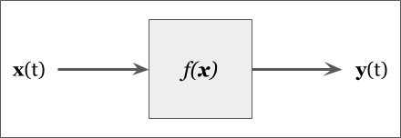
A lot of things seem to work that way: a light bulb filament gives off light proportionate to the energy applied to it. This lack of statefulness implies time invariance: It doesn't matter when energy is applied, the filament gives off light.
It's a convenient way to understand systems. This is how data driven systems are designed: Data goes in, transformed data comes out. But time invariance places specific requirements on the inputs themselves. When such a system is given an impulse, it changes its response only then and provides a transient response afterwards (which can include no response at all!). Take for example listening to the radio: if the signal is disrupted, but what if we don't want the music to abruptly stop? Many streaming services have buffering built into them to cache the stream so that disruptions in the signal are masked by the buffer itself. In a sense, this buffer cache is providing a state to the application: as long as it isn't empty, normal operations can progress!
Digital control systems are usually designed considering that the input signal may be latent or dropped an update, but they still have requirements to produce their output following some periodic. Because of this, a lot of signal processing implementations follow this model.
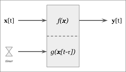
The above model now has two triggers for generating an output: one is upon receipt of new data, and another is when the timer expires. This simple model guarantees a data rate of at-least the timer rate, which is applicable in a lot of design circumstances. But the internal state of the controller changes based on the trigger because the logic for when no new data is available will activate or deactivate based on the trigger.
State Modeling
Lets take a look at some sample code describing a system like in Figure 2.
Listing 1 - Example of a Stateful Program
Here's a basic example of it running (pardon the bit of Python to invoke it).
# Built before running the notebook...
!../code/SwSys_StateModeling/StateModelingExample 3
!../code/SwSys_StateModeling/StateModelingExample 5
In general, the above code is very functional and has a simple decision flow that can be described like this:
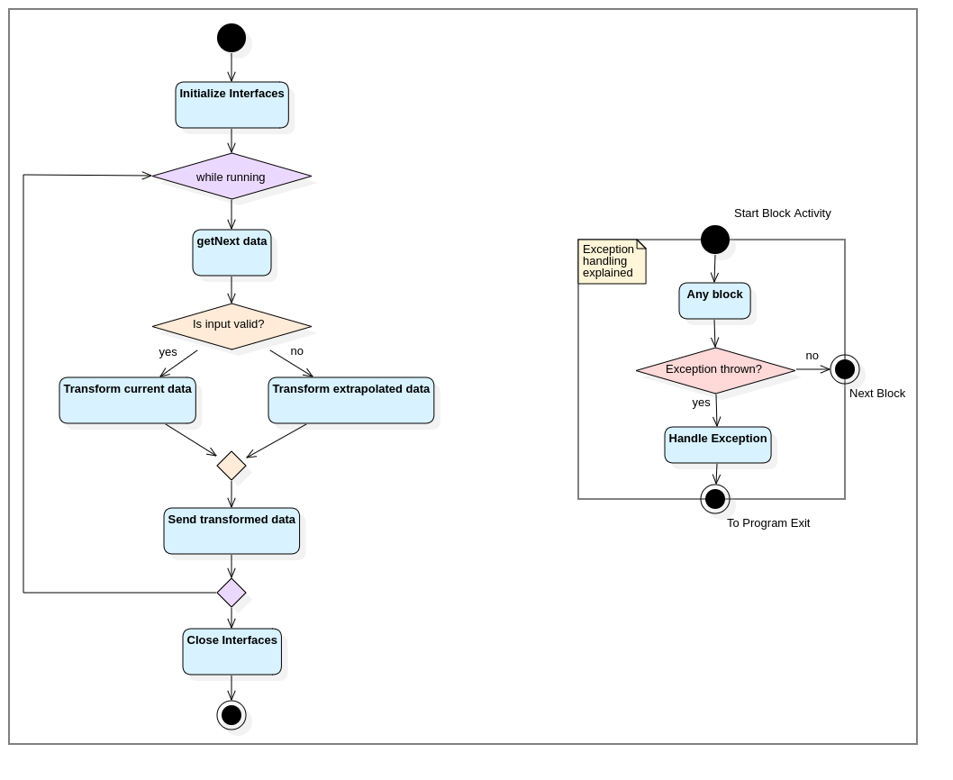
The code itself has a very simple flow: open the interfaces, main-loop process with backup processing when data is unavailable, and close the interfaces. And if anything goes wrong, the process handles exceptions before shutting down.
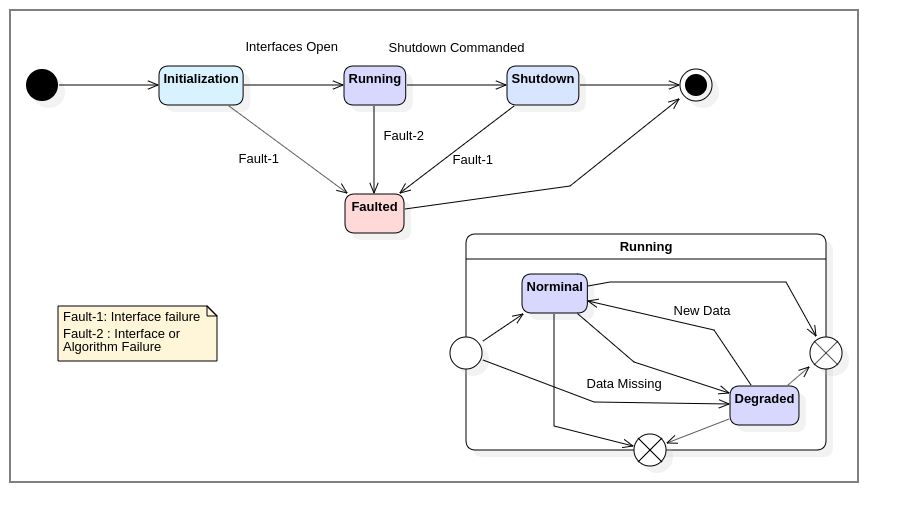
What's interesting is that each major block is a unique phase of operation. It takes some amount of time to execute, and transition to the next operation depends on how the previous concluded. In essence, we can show that this program has different states of operation at any given time. Thus, we can also describe this process with a state model:
It's been said hundreds of different ways, but this resonates in many cases [3]:
It should be understood that the model is, at best, a surrogate for the actual system, whose precision is subject to the assumptions and approximations made by the control designer.
- Optimal Control & Estimation
And that's just it, what we see above is merely a model describing the internal state of the process. It reveals a different facet, a different interpretation of the design which can highlight behaviors not considered by other models (in this case, the Decision Flow model)
State Machines vs State Models
Now that we can see that software can be described as having a runtime state, what then is the difference between this and a machine? Concisely, a state machine is a construct which senses events/triggers, then follows a pre-defined set of rules governing transition, and finally executes a specific set of system behaviors which may provide an additional trigger. This is a nuanced definition, and we'll explore the differences between a stateful system versus a state machine.
The key differentiation here is that something has to reconcile ALL events/triggers. In design, it isn't sufficient if some parts can detect a trigger (like the wrapping try-catch in the listing above). For example, in Listing 1, immediately after calling connect() with each of the interfaces, the program immediately transitions into the execution loop without any evaluation of events.
Another differentiator is that state machines are a software design pattern! Listing 1 is purposefully implemented naively to highlight the anti-pattern. To maintain flexibility, the insertion or removal of a state and its associated triggers should not require a redesign of the underlying code. This design pattern isn't unique (it often is implemented via other equally flexible design patterns), but let's explore one of these.
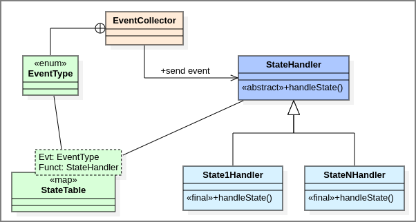
Listing 2 - State Machine Pattern
Listing 2 is quite longer than Listing 1, but it is no more complex. Rather, the added length introduces a level of robustness and extensibility unavailable in Listing 1. Here, requirements are free to change with little impact to the underlying architecture. So if multiple fault-response states are needed, or if we introduce additional events triggering new states, it just becomes a matter of updating the StateTable mapping. Stricter state-transition control can be implemented in the EventCollector class (such as recognizing current state and determining if the combination of state and event warrants a change of state).
Weaknesses of State Machines
The example application above was not selected arbitrarily. In fact, it contains properties that are amenable to using the State Machine Pattern.
Other than clearly identifiable states and conditions of transition, one additional requirement is necessary for this pattern: States implement non-pipeline operations. This is a very specific threading/parallelization requirement because triggers may interrupt the completion of a state's operation, and if the pipeline is not completely synchronized, its reactivity is gated on the slowest stage of the pipeline. This becomes increasingly complicated when Pipeline-Reduce patterns are employed (e.g., receiving push-updates of sensory-data, post-processing each, then rendering a decision).
Like all things engineering, shoehorning a solution into a design is a pathway to anti-patterns. So care must be taken when considering this approach. We'll explore these in later posts.
Conclusion
All complex systems have state, but designers should not assume that such systems truly implement a state machine. In the case of safety-engineering, this does pose unique challenges: Some systems are easily refactorable to adopt the explicit control offered by a state machine, however others cannot due to the complex nature of the algorithms they implement.
But some fringe benefits are apparent when implementing a state machine pattern: we can now instrument event listeners to act in parallel and have a central controller dictating which event takes precedence. This phenomenon is a significant source of "throw everything away and start over" development when requirements change, or when naive prioritization is implemented and testing reveals flaws.
References
1. Lafreniere, David. "State Machine Design in C++". Code Project, 2019. [Online] Available: https://www.codeproject.com/Articles/1087619/State-Machine-Design-in-Cplusplus-2
2. "Chain of Responsibility". Open Source Matters, 2006. [Online] Available: https://www.oodesign.com/chain-of-responsibility-pattern.html
3. Optimal control book...
Comments !